Facadist casemod
My journey restoring a 30 years old PC case front panel and modernising it to work with today's hardware.
 Hey folks!
If you are here, you likely want to learn about this journey to learn something useful to your own. I’ll share as many details as I can.
Hey folks!
If you are here, you likely want to learn about this journey to learn something useful to your own. I’ll share as many details as I can.
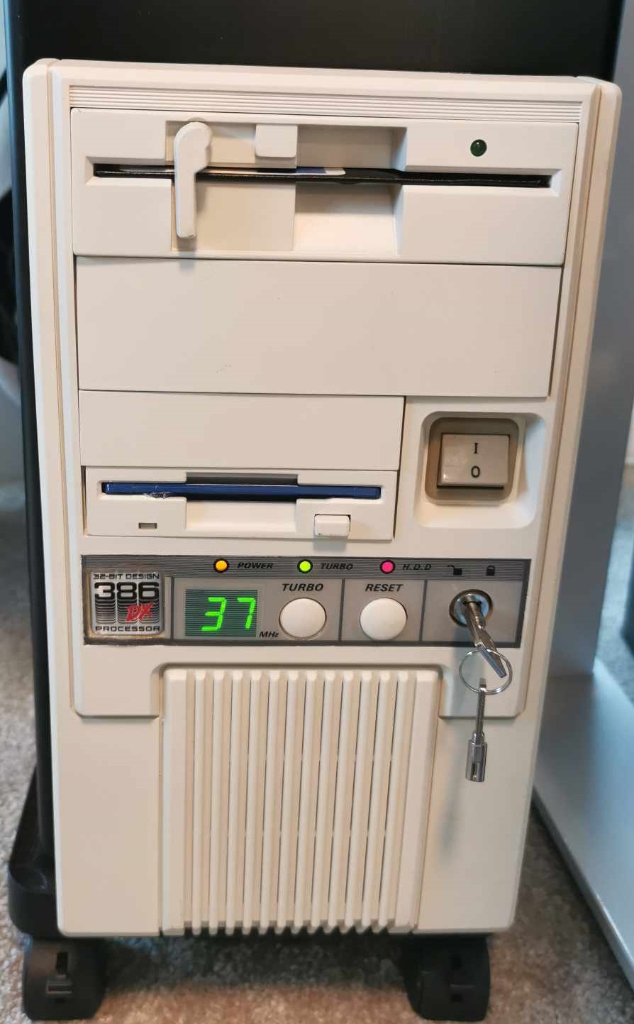
This is the result:
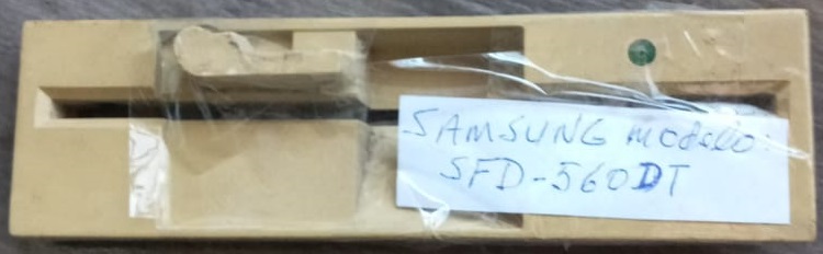
The front panels of the floppy drives were removed from drives that NO LONGER WORKED.
My journey started when I saw this post: SErEndIPITy - 386 case with modern internals and front LED converted to CPU temp display - Imgur
However, I wanted to do it with my very first computer case, which I didn’t have anymore. I found a very old one, not in great shape, that looked exactly the same and decided to restore it.
After carefully considering how much metal I’d have to cut through and adaptations for airflow, I decided not to do a sleeper. It was a “mini-tower” case, AT form factor. Fitting a good mobo would be challenging, and finding a good PSU is even worse.
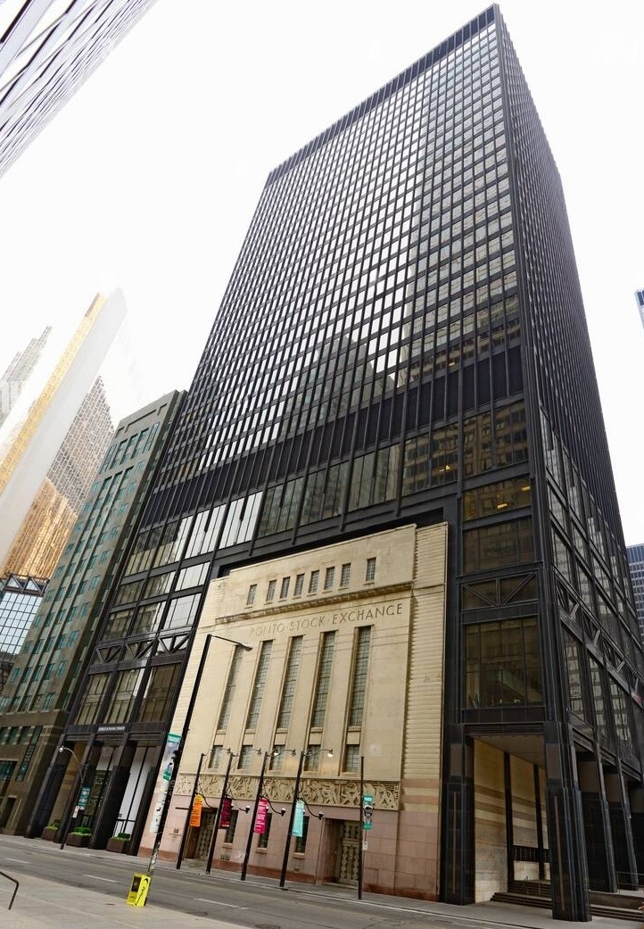
Fortunately, living in Toronto, I’ve learned to appreciate Facadism, which inspired me to do something crazy: Use the front panel of the PC case as a facade for my current PC case.
Facadism, façadism, or façadomy is the architectural and construction practice where the facade of a building is designed or constructed separately from the rest of a building, or when only the facade of a building is preserved with new buildings erected behind or around it.
There are aesthetic and historical reasons for preserving building facades. (…) the practice is sometimes used by property developers seeking to redevelop a site as a compromise with preservationists who wish to preserve buildings of historical or aesthetic interest. It can be regarded as a compromise between historic preservation and demolition and thus has been lauded as well as decried.
 If I ever put my hands on this, I would definitely build a sleeper:
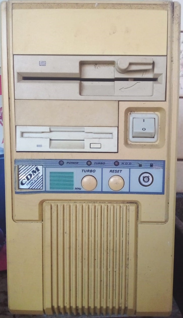
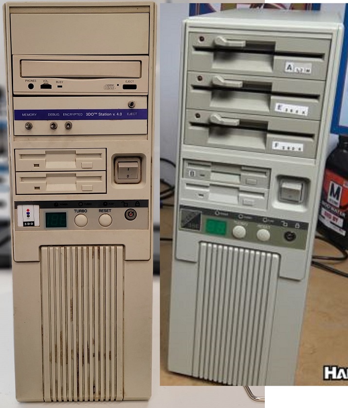 Meanwhile, this is what I got:
Front panel features
Original:
- On/Off switch: This switch was connected directly to the PSU and would simply cut off power to the PC.
- Reset button, HDD LED, Power LED: Worked as they work today.
- Turbo button: Back in the days, some software, especially games, used to rely on the CPU frequency to regulate their speed. As CPUs got faster, they needed to be slowed down to make older software work properly The turbo button would be connected to motherboard jumpers and be used to REDUCE the CPU frequency when off (usually, it would be kept on).
- Numeric LED display: The turbo button was also connected to the numeric LED display, switching between two configurations of LEDs displaying two different pre-set values. The configurations were set directly on the back of the display and could be any, regardless of the actual clock. Usually, it was set to the CPU clock/frequency, but as many of these only had 2 digits, computers with a frequency of 100MHz or higher would be set to “HI” and “LO.” Some displays had a “1” digit in the hundreds place.
- Turbo LED: Connected to the motherboard, it would reflect the state of the turbo button.
- Key lock: It would prevent the computer from being booted. The BIOS would implement the locking.
New features
- On/Off switch: Turns the PC on and Off. It required a circuit to adapt the switch (latch) to a momentary pulse. I’m providing all the details below.
- Reset button, HDD LED, Power LED: Work out of the box.
- Turbo LED: Using a microcontroller, it reflects the state of the Turbo button. I know I could simply have them connected in series, but I wanted to give the turbo button some function so it’s connected to a microcontroller. At the moment, I’ve set it up to turn the screensaver on and off.
- Key lock: Also connected to the microcontroller, it switches between speakers and headphones.
- Numeric LED display: Also connected to the microcontroller, it’s being used to show the CPU temperature.
Everything I had to connect to the motherboard was connected in parallel with the current case buttons/LEDs using Dupont Wire 2 Pins Single Female to Dual Male and a 9pin Integrated ATX Motherboard Jumper Extension Cable.
It’s important to highlight that the front panels of the floppy drives were removed from drives that NO LONGER WORKED. They were carefully disconnected, their LEDs, buttons, latch, and doors preserved, and now there’s a routine I can start that makes the LEDs turn on to emulate the appearance of the PC booting up. That’s what you saw in the video above. The audio is simply a sound file played in sync.
Restoration
For the restoration, I could have gone with Retrobright. I suggest you watch it so you can also see some of the disassembly process:
However, I’ve read mixed success reports from using it, so I just painted it. Unfortunately, it didn’t occur to me to take pictures or record the disassembly. I can tell you it involved:
3.5” floppy drive:
- Detaching a small transparent plastic where the LED is.
- Disconnecting the door and saving the spring.
- Disconnecting the button.
5.25” floppy drive:
- Disconnecting the latch.
Front panel:
- Removing the LEDs (pulling from the back).
- Unscrewing the lock (from the back) and pulling it out (from the front). The keys are hard to find, and if you want, you can replace the whole thing: https://www.amazon.ca/dp/B07LD51VZD. I got lucky, and the keys worked on the original lock, but this new one is identical.
- Pulling the buttons from the front to release the switch mechanisms (pulled from the back).
- Pulling the power button out from the front.
- Unscrewed the numeric LED display.
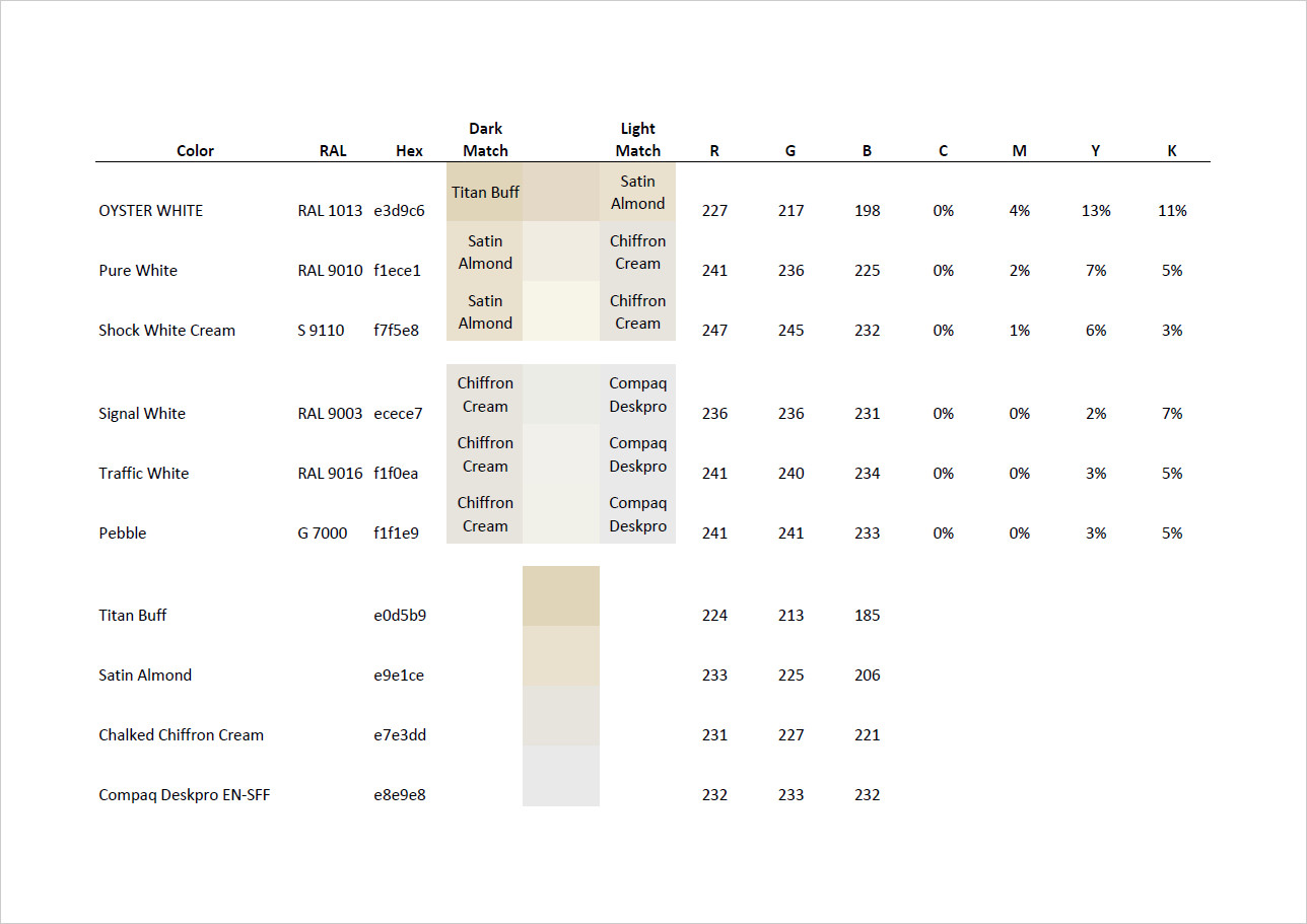
I’ve used sandpaper (grit 400) on everything, very slightly, covered what I had to protect with painter’s tape, and painted with Rust-Oleum Chalked Ultra Matte Paint in Chiffon Cream, 340G Aerosol Spray Paint after reading a very interesting thread on the best paints/colors for these old beige computer cases here: Best off the shelf spray paint for beige computer cases \ VOGONS.
 In case the site ever goes offline, I’ve saved it here:
To honor my old 386, I bought this patch as a final touch.

On/Off switch
The On/Off switch doesn’t work out of the box. As I explained before, while on, it keeps the circuit closed. It would be the equivalent of pushing the on/off button and holding it. After 4 seconds, the PC turns off.
I wasn’t considering using a microcontroller (ESP32 with Tasmota) to display the CPU temperature when I decided to build a circuit to adapt the button. Since the circuit worked perfectly, I decided to keep it running.
I want to give a big thanks to my father-in-law who gave me some important tips about building this circuit. Thank you, Paulo!
I needed to close the motherboard jumper momentarily whenever the switch switched.
The concept came from here:
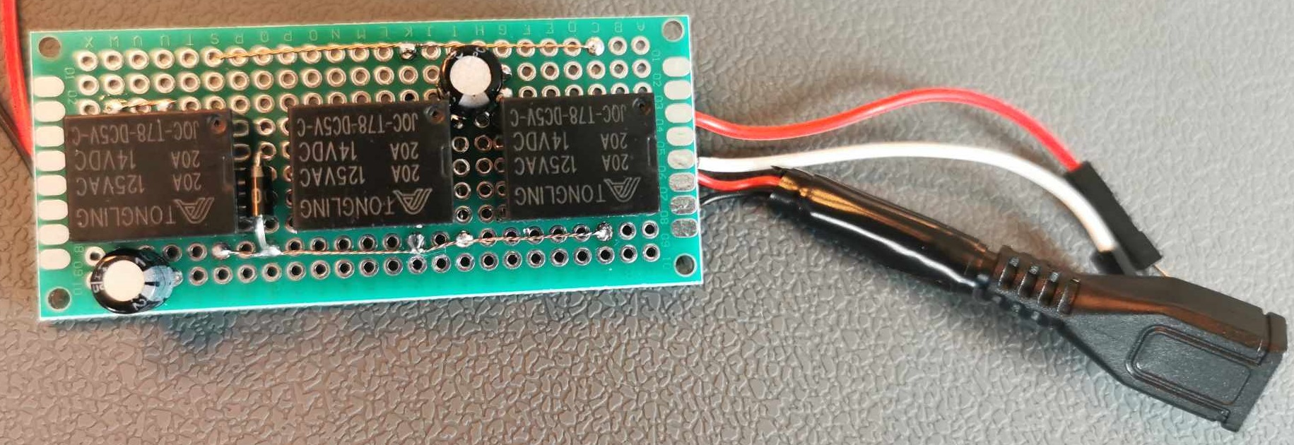
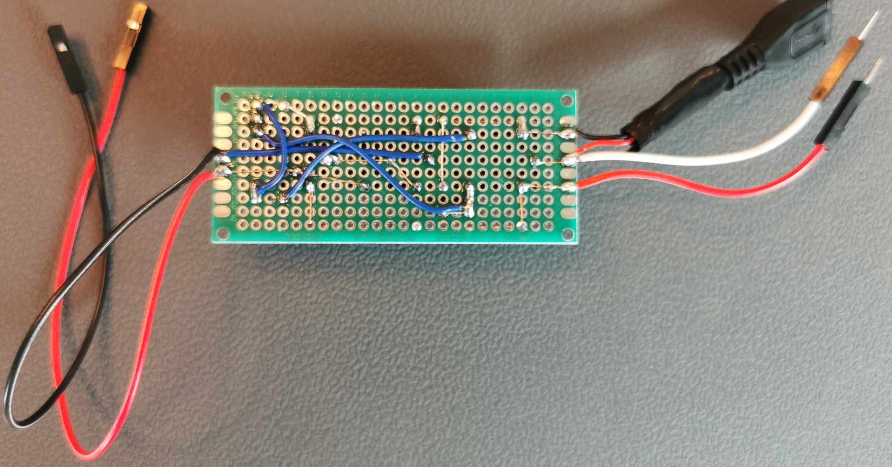
This is the circuit described in the video:
 See the Falstad circuit simulation.
To power the circuit, I’ve set up the PC to keep the USB ports powered even when the PC is off and connected it to an internal USB port. You can use any of these:
- https://www.amazon.ca/dp/B072Q1MBSG
- https://www.aliexpress.com/item/1005004843988782.html plus https://www.amazon.ca/dp/B073PQWY2B (this is the option I chose in the end, as it gives me an extra port and a short cable to power the ESP32).
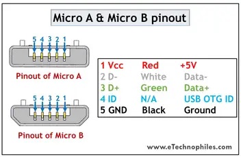
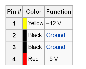
I used a female port from a Micro-USB extension cable to connect the circuit to the USB port because I felt it was easier to cut and solder the wires. In case you want to do the same, here’s the pinout:
 Bill of Materials (BOM):
- Micro-USB extension cable: https://www.amazon.ca/dp/B0C5N5W1T6
- Capacitor 220µF: https://www.amazon.ca/dp/B07YN6NPTL
- Relay 5v: https://www.amazon.ca/dp/B0874MF8DR
- Diode 1n4007: https://www.amazon.ca/dp/B08KFL5WZ6
- PCB Prototype Board: https://www.amazon.ca/dp/B07Y3DRMWB
Numeric LED Display
To power the numeric LED display, I decided to pull energy from the PSU instead of an internal USB port as I did for the on/off switch circuit and the microcontroller. The idea was to ensure the display would be turned on and off with the computer (unlike the power button that needs power regardless). The PSU has Molex plugs with 12v and 5v. I didn’t want to cut wires from the PSU, so I bought these Molex Splitter/y-cables to cut and plug on the PSU cable. Here is the Molex pinout (I used the red and the black beside it for +5v):
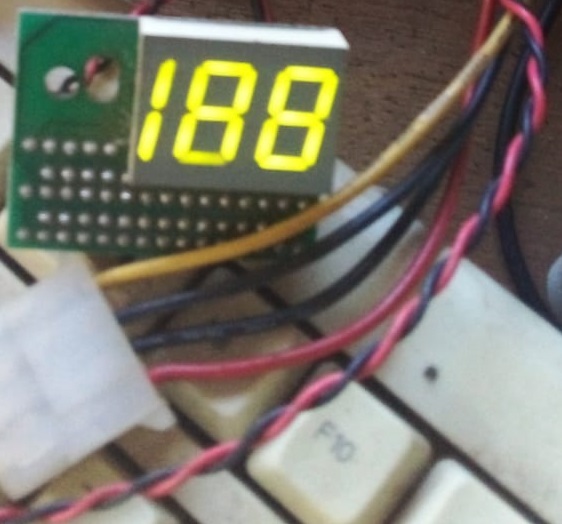
 The original numeric LED display only had 2 digits. I decided not to mess with it and got this 2.5-digits (188) instead. They are exactly the same size.
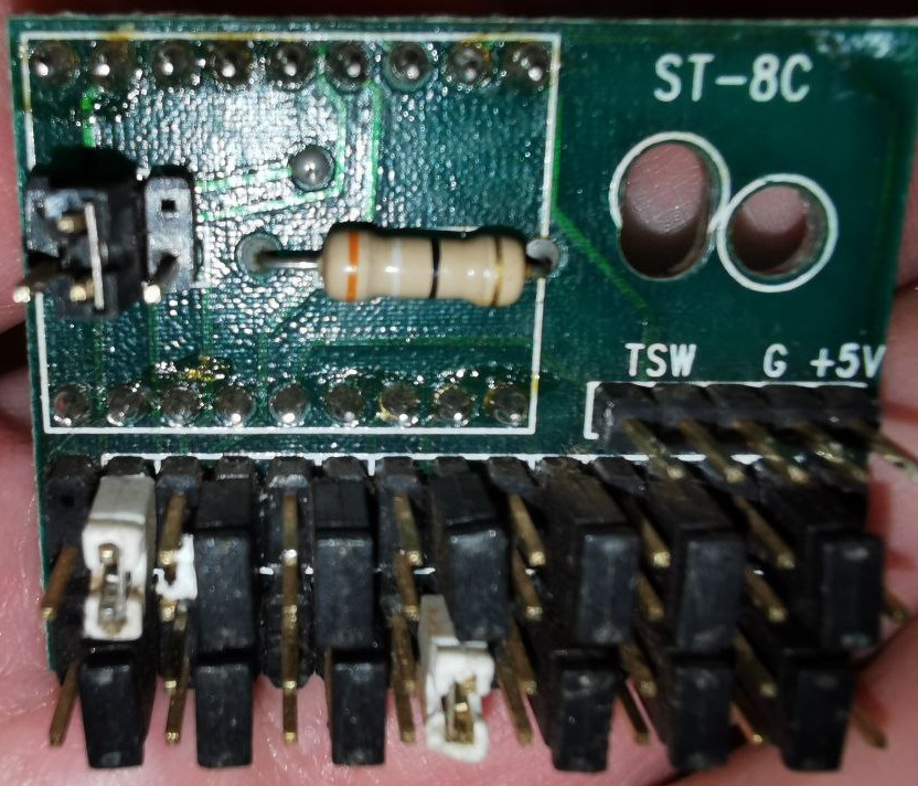
 Each 7-segment digit works like this:
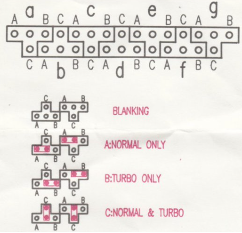 There are 4 jumpers in a T formation for each segment. The pin common to all the combinations, at the center/crossing of the “T,” is the only one that needs to be connected to the ESP32.
The first row controls the tens place, and the second controls the unit place. Yours might be different, but it will most likely have one row for each digit with this configuration.
The hundred placement has both segments controlled by a single T.
Think about the digit 8. The horizontal top LED segment is the first jumper and goes clockwise, with the middle being the last LED segment. The second is the top right, the third is the bottom right, the fourth is the horizontal bottom, the fifth is the bottom left, the sixth is the top left, and the seventh is the horizontal one in the middle.
CPU Temperature (ESP32 + MCP23017 running Tasmota)
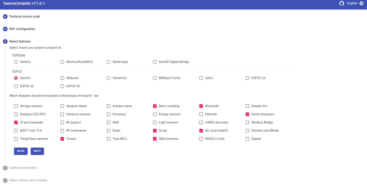
I flashed Tasmota on the ESP32. I had considerable help from my friend Philip, as I never worked with a microcontroller before. He compiled the firmware for me with the correct options and helped me diagnose some issues I had. Thank you, Philip!
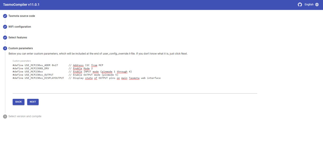
He used a docker (https://hub.docker.com/r/benzino77/tasmocompiler ) with the tasmo-compiler (https://github.com/benzino77/tasmocompiler) with the following settings:

 For the switches to work properly, I had to issue the commands
SwitchMode1 2
SwitchMode2 2
SetOption114 1
Restart 1
To keep the web server up, I had to use
SetOption41 60
Restart 1
You can read about these settings here:
https://tasmota.github.io/docs/Buttons-and-Switches/#ac-frequency-detection-switch.
To work with the MCP23017, I had to set them as inverted relays. My mcp23x.dat has only this line:
{"NAME":"MCP23017 A=Ri1-8, B=Ri9-16","BASE":1,"GPIO":[256,257,258,259,260,261,262,263,264,265,266,267,268,269,270,271]}I also had to change the pinmode using the commands: Sensor29 Reset5 restart 1
The firmware was compiled with Berry Script support, which I used to create a function that receives the request from my PC with which LEDs need to be turned on or off to display the CPU temperature and additional functions with associated rules to send a request to my PC informing the state changes from the turbo button and the key lock.
Here is my Berry Script. I could probably use parameters for the switch functions, but I didn’t take the time to learn how to pass them on the rules.
def CPUtemp(leds)
  tasmota.cmd("Sensor29 0," + str(leds[0]))
  tasmota.cmd("Sensor29 1," + str(leds[1]))
  tasmota.cmd("Sensor29 2," + str(leds[2]))
  tasmota.cmd("Sensor29 3," + str(leds[3]))
  tasmota.cmd("Sensor29 4," + str(leds[4]))
  tasmota.cmd("Sensor29 5," + str(leds[5]))
  tasmota.cmd("Sensor29 6," + str(leds[6]))
  tasmota.cmd("Sensor29 7," + str(leds[7]))
  tasmota.cmd("Sensor29 8," + str(leds[8]))
  tasmota.cmd("Sensor29 9," + str(leds[9]))
  tasmota.cmd("Sensor29 10," + str(leds[10]))
  tasmota.cmd("Sensor29 11," + str(leds[11]))
  tasmota.cmd("Sensor29 12," + str(leds[12]))
  tasmota.cmd("Sensor29 13," + str(leds[13]))
  tasmota.cmd("Sensor29 14," + str(leds[14]))
end

def switch1Off()
  tasmota.cmd("Power1 0")
  tasmota.cmd("WebSend [192.168.1.11] /?Switch1=0")
end
tasmota.add_rule("Switch1#State=0", switch1Off)

def switch1On()
  tasmota.cmd("Power1 1")
  tasmota.cmd("WebSend [192.168.1.11] /?Switch1=1")
end
tasmota.add_rule("Switch1#State=1", switch1On)

def switch2Off()
  tasmota.cmd("WebSend [192.168.1.11] /?Switch2=0")
end
tasmota.add_rule("Switch2#State=0", switch2Off)

def switch2On()
  tasmota.cmd("WebSend [192.168.1.11] /?Switch2=1")
end
tasmota.add_rule("Switch2#State=1", switch2On)
You have two options to load this script. Either you save it on your autoexec.be file, or you save it as a separate be script and load it in your autoexec.be file with this line (replace script.be with your script’s file name): load(“script.be”)
To send commands to the ESP32, I’m using its http server. I intend to use a serial connection in the future. For now, this is how I send commands: http://ESP32IP/cm?cmnd=write_your_command_here
If you want to send a Berry command (like to run a Berry function), just do: http://ESP32IP/cm?cmnd=BR%20write_your_command_here
E.g., this is how I set the temperature on the display to 51: http://LAN ESP32 IP/cm?cmnd=BR%20CPUtemp(“010110110110000”)
The ESP32 pinout in the Amazon ad was correct, but it failed to inform me that some pins were input-only. This other one helped me a lot:
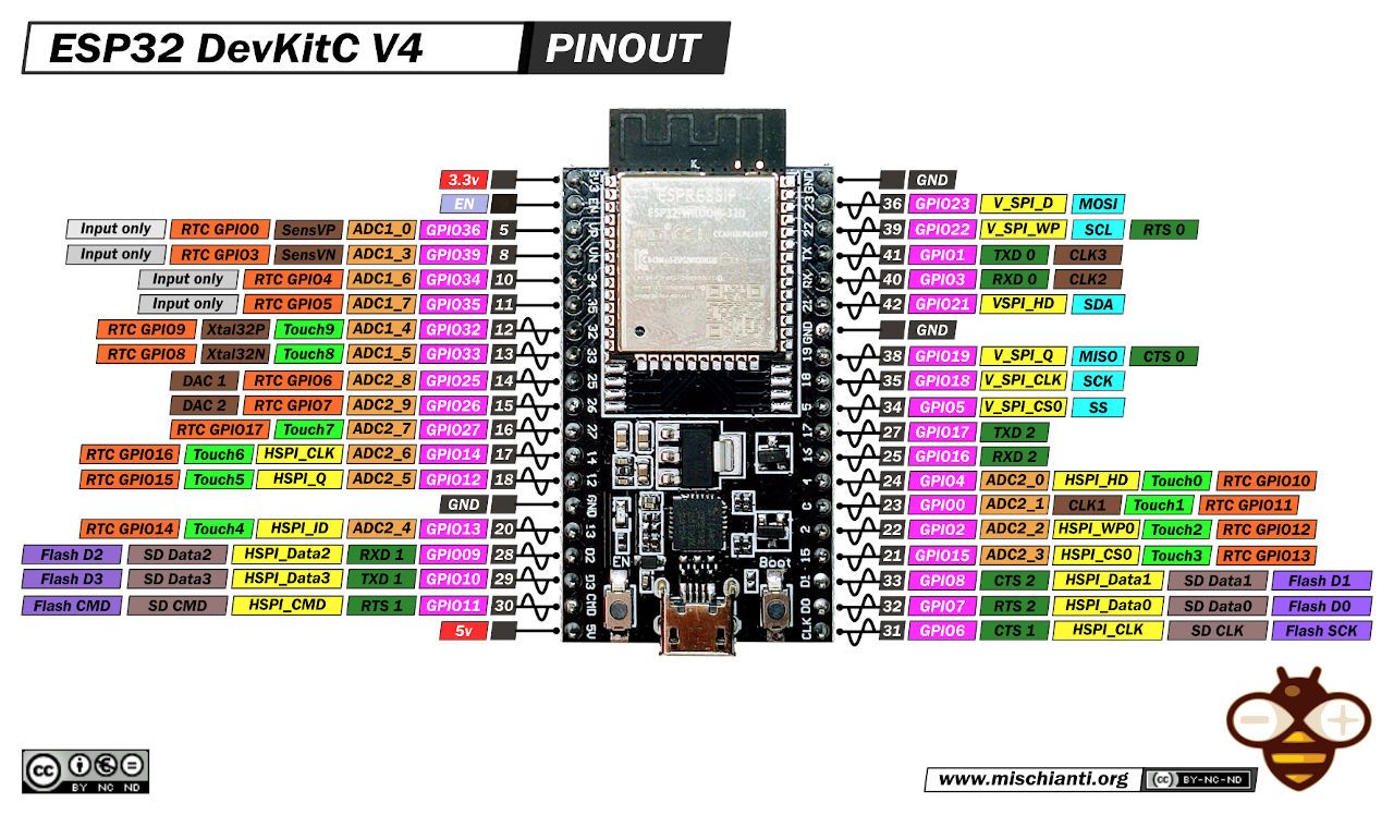
This is not the only possible configuration for the ESP32 pins, but it’s one that I’m using:
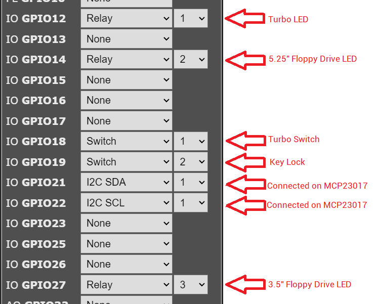
Bill of Materials (BOM):
- 38-pins ESP32 KeeYees Development Board Microcontroller ESP-WROOM-32 Chip CP2102: The microcontroller itself.
- CQRobot Ocean: MCP23017 IO Expansion Board: It was necessary to connect the numeric display LEDs as there aren’t enough pins on the ESP32.
- Dupont Breadboard Jumper Wires: Used to connect the MCP expansion board to the numeric LED display and to connect the panel’s LEDs, turbo switch, and key lock to the ESP32.
- Dupont Wire 2 Pins Single Female to Dual Male: Used on GND pins.
Lastly, this is the repository with the code I’m running from my PC: https://gitlab.com/pplupo/facadist-casemod.
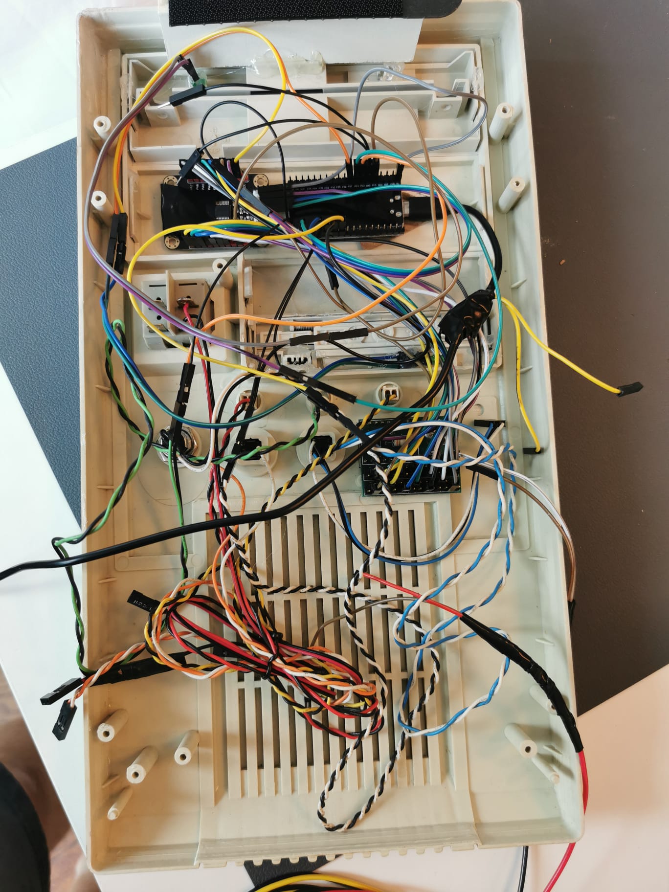
This is how it currently looks on the back. If you have a suggestion on how to make it look better, please share in the comments. It doesn’t even have to be very good, anything you say might inspire something better. Let’s do a brainstorming! :-)
I sincerely hope you enjoyed this post. If you have any questions, feel free to comment.